Application of a detailed model of a steering system in highly dynamic HiL tests of EPS motors
21st Stuttgart International Symposium, Stuttgart, 30-31 March 2021
M. Hemmersbach, H. Briese, M. Haßenberg,
DMecS Development of Mechatronic Systems GmbH und Co. KG,
Gottfried-Hagen-Straße 20
51105 Köln
info@dmecs.de
www.dmecs.de
M. Irmer, H. Henrichfreise,
Technische Hochschule Köln
Labor für Mechatronik (Cologne Laboratory of Mechatronics, CLM),
Betzdorfer Str. 2
50679 Köln
info@clm-online.de
www.clm-online.de
Abstract
Hardware-in-the-Loop tests (HiL tests) are common practice in the development process of “Electric Power Steering - EPS” systems. The HiL tests are carried out on power pack test benches, which emulate the real environment, that an EPS motor is exposed to in a real vehicle.
This paper describes highly dynamic HiL tests of an EPS motor using the power pack test bench of [1]. To precisely emulate the real environment of the EPS motor, the detailed steering model of [2] is used and moreover embedded in a vehicle dynamics model. The resulting HiL system consists of the detailed steering model, the vehicle dynamics model, the power pack test bench, and the corresponding test bench actuator control. The HiL system is used to perform the highly dynamic HiL tests and allows realistic parameter sets for every involved model.
During the HiL tests, the fishhook and the double lane-change are performed. Both are standardized road tests, that include a severe change of the driving direction of the vehicle and are hence highly dynamic excitations of the EPS system. As a consequence, the measurement results of both HiL tests are used to prove the performance of the power pack test bench in highly dynamic HiL tests.
1 Introduction
Beside the controller design itself, the development of a control system requires extensive tests to evaluate the functional behavior of the control system. To perform tests, that expose the control system to a realistic environment, Hardware-in-the-Loop tests (HiL tests) are common practice. A HiL test is usually carried out on a specific test bench, that emulates the real environment of the control system by the application of realistic operating loads to the actuator of the control system.
In the automotive industry “Electric Power Steering - EPS” systems are widely used to support the driver when steering. The actuators of EPS systems are electric motors, that usually have an integrated EPS controller. The EPS motor and EPS controller are manufactured as one component and named “power pack”. During the development process of the EPS control, power packs are subject to test in HiL tests performed on a power pack test bench.
To create a realistic testing environment the power pack test bench itself is not sufficient. Furthermore, detailed models of the environment of an EPS motor in a real vehicle and a controller of a test bench actuator are necessary. The realistic testing environment therefore consists of the power pack test bench, the test bench actuator control and the corresponding models and forms a so called HiL system.
To emulate the operating loads of the EPS motor in HiL tests correctly, the HiL system must meet the following two requirements.
Test bench actuator control with sufficient dynamical behavior, sufficient robustness and control accuracy.
Detailed model of the environment of the EPS motor in a real vehicle.
Only if both requirements are fulfilled, a stable HiL system can be guaranteed and reliable HiL testing results can be achieved.
This paper describes a HiL system, that meets both above-mentioned requirements. The HiL system is used in highly dynamic HiL tests, that are carried out on a power pack test bench designed by a company named “DMecS”. [1] To create the HiL system, a purposive regulator design of the test bench actuator control is described. Additionally, a detailed model of an EPS steering system [2] and a vehicle model are incorporated to emulate the realistic environment of the EPS motor. The performance of the HiL system is eventually proven in two highly dynamic HiL tests, that are standardized road tests (fishhook, double lane-change) in the automotive industry.
2 Power Pack Test Bench
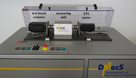
Figure 1 shows the power pack test bench, that is used to perform the HiL tests described in chapter 5.
As shown in figure 1, the basic components are the test bench actuator, a measuring unit, and the EPS motor. The test bench actuator and the EPS motor are connected via the measuring unit. Because of this connection, the test bench actuator can apply a torque to the EPS motor and therefore emulate the operating loads of the EPS motor during a HiL test.

Figure 1 shows furthermore, that not a typical power pack from a production car is installed on the test bench. The installed EPS motor does not include an EPS control and is consequently not a power pack. However, the performance characteristics of the installed EPS motor are comparable to a typical power pack, which ensures the credibility of the HiL tests performed on this test bench.
2.1 Test Bench Actuator Control
As a part of the HiL system, the test bench actuator control is crucial to apply realistic operational loads to the EPS motor in a HiL test. For this reason, a highly dynamically test bench actuator control is used, that can regulate different controlled variables located at the shaft of the EPS motor. Depending on the HiL system, the controlled variable at the shaft of the EPS motor can be the position, the velocity, or the torque. [1]
Despite of disturbances like friction, torque ripple and measurement noise, the test bench actuator control must provide a high controller bandwidth as well as a high control accuracy. Natural oscillations of the power pack test bench should be damped actively by the control. To meet these demands, the test bench actuator control is realized as an observer based state space controller. [1] In addition to that, the test bench actuator’s torque ripple is compensated using a nonlinear model, which improves the control accuracy of the test bench actuator control.
3 HiL-Application
Figure 2 provides an overview of the HiL system used in the HiL tests of chapter 5. According to the boundaries of software and hardware, figure 2 is divided in the sections “dSPACE real time system” and “power pack test bench”.
...
