Design and Analysis of a Controller for Electrohydraulic Brake Systems on AUTOSAR Architecture Level
Published at 13th Stuttgart International Symposium, Stuttgart, 26.-27. February 2013
Dipl.-Ing. Emad Farshizadeh, Dipl.-Ing. Hermann Briese,
DMecS - Development of Mechatronic Systems GmbH & Co. KG, Köln;
Dipl.-Ing. Steffen Beringer, Dipl.-Ing. Dominik Holler,
Dipl.-Ing. Lars Stockmann,
dSPACE GmbH, Paderborn
1 Introduction
Due to dwindling fuel resources and the need to reduce emissions, today’s automotive industry is on the move from traditionally combustion engine-powered cars towards alternative drive technologies.
Nevertheless the number of purely electrically powered cars is still low. The reasons for this are manifold. New controllers have to be developed, e.g., for energy management, engine and brake control. These controllers have then to be integrated into existing environments. This process usually takes a lot of time due to the high safety requirements in the automotive industry. Furthermore the development of control algorithms is getting more and more complex. For example, engine controllers must be adapted and optimized for each specific electric motor to make driving more energy-efficient. To optimize the energy efficiency when braking, the brake controller has to allow recuperation and thus has dependencies on both the brake and the engine. Altogether the development of new complex controllers is a longer and thus costlier process. New concepts and methodologies must therefore be investigated and applied to accelerate the development of complex electronic control units (ECUs) and boost technological and economic progress in electric vehicle engineering.
These challenges are addressed in the research project “Simulationsgestützter Entwurf für Elektrofahrzeuge” (Simulation-Based Development for Electric Vehicles). In the project, new controller and environment models for electric vehicles are developed and tested by using a dedicated tool chain. The tool chain is further enhanced and adapted to the domain of electric vehicles to support the rapid development of the control software. The project partners are DMecS GmbH & Co. KG, the LEA institute, the C-Lab (University of Paderborn) and dSPACE GmbH. This paper describes a part of the project where two controllers, one for the electrohydraulic brake system and one for energy management, are developed. The controllers and their plant models provide recuperative braking and are examples of new complex components in electric vehicles. Another aspect is that AUTOSAR has become the de facto standard in the automotive sector, and as a consequence, the demand for AUTOSAR-compliant software is continuously growing. This paper therefore presents an AUTOSAR-compliant ECU application software implementation in which the controllers modeled in Simulink® are converted into a virtual ECU including basic software parts.
2 Electrohydraulic Brake System
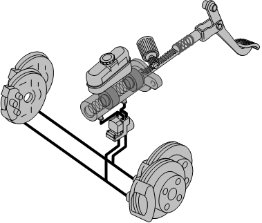
Figure 1 shows the setup of the electrohydraulic brake system (EHBS), which provides braking assistance by a controlled motor. The brake pedal force applied by the driver is transmitted through the pedal gear and an elastic push rod to the primary pistons of the master brake cylinder. This force is assisted by the electric power brake booster (EHBS actuator), which consists of a current controlled motor and a transmission that converts the motor torque to a force on the piston. The resultant displacement of the pistons in the master brake cylinder generates a pressure build-up which provides the braking torques at the wheel brakes. By using the pressure in the master brake cylinder as a controlled variable for a superimposed control of the EHBS actuator, a highly dynamic pressure build-up is achieved.
In the next section the plant model for the pressure controller design is introduced. After that, a symmetrical optimum design of a PID controller with active damping for EHBS is presented.In the next section the plant model for the pressure controller design is introduced. After that, a symmetrical optimum design of a PID controller with active damping for EHBS is presented.

2.1 EHBS Plant
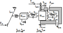
The physical substitute model of the plant, which is used for the model-based design of the EHBS controller, is presented in figure 2. This model contains the relevant parameters and the degrees of freedom sped and spist as well as the external forces Fdr and Ffr,red and torque Tepb that contribute to the system. Here the parameters mred, bred and Ffr,red represent the inertia, damping and friction of the motor and piston. The hydraulic capacity Cred represents the capacities of the master brake cylinder chambers, the lines to the wheel brake cylinders and the wheel brake cylinder chambers. The corresponding mathematical model of the EHBS plant is given by the equations


where the controlled motor torque Tepb is generated with the equation

from the reference input Tepb,req.
2.2 EHBS Controller
The plant model shown in the previous subsection forms the basis for designing the pressure controller. The aim of the controller is to ensure steady-state accuracy as well as a fast and well-damped transient response to the reference pressure and to reject unknown disturbances. Therefore, a PID controller with the transfer function

is used and its parameters are determined by applying the symmetrical optimum method. Due to the fast resonant mode caused by the compliant coupling of the brake pedal and piston, the plant model of EHBS deviates from ideal plant for symmetrical optimum design. Hence, the resonant mode is damped by the feedback of the derivative of the pressure. The rough structure of the control loop with active damping is given in figure 3, where the derivative of the pressure is calculated by a real differentiator.
The driver’s desired braking value is detected by measuring the brake pedal force Fsen at the elastic push rod. The reference signal pcha,ref for the EHBS controller is generated as a function of the brake pedal force and mimics a conventional brake system with pneumatic brake booster. The structure of the control loop with reference variable is ...

