Onboard, Real-time Loads Monitoring Using the Loads Observer – Practical Implementation Aspects
International Forum on Aeroelasticity and Structural Dynamics (IFASD) 2009, Seattle, USA, June 21 – 25, 2009
M. Augello, L. Bensch
Airbus Operations GmbH
21129 Hamburg, Germany
e-mail: michael.augello@airbus.com and lars.bensch@airbus.com
J. Jusseit
DMecS Development of Mechatronic Systems GmbH & Co. KG
51105 Cologne, Germany
e-mail: juergen.jusseit@dmecs.de
H. Henrichfreise
Cologne University of Applied Sciences, Cologne Laboratory of Mechatronics
50679 Cologne, Germany
e-mail: hermann.henrichfreise@clm-online.de
Abstract
Nowadays, Loads Monitoring (LM) of aircraft structures plays an important role not only in military, but also in civil aviation with regard to maintenance and inspection activities. It is integrated in numerous applications like fleet wide monitoring and leads to a reduction of aircraft on-ground time after an in-flight incident. This paper describes the process taken to adapt, integrate and test the LM algorithm “Loads Observer” on a prototype system within the framework of the European AWIATOR (Aircraft WIng with Advanced Technology OpeRation) research program. In this context, the algorithm was implemented on real-time hardware, which was installed onboard a flying testbed and fed with signals from the aircraft’s flight test data acquisition unit. For the real-time operation of the system, the pre-processing of the aircraft’s input signals was enhanced enabling the on-line synchronization and interpolation of the data. The pre-processed input signals were provided to the Loads Observer algorithm for the simulation of the aircraft’s motion including the flexible deformation, thus allowing the reconstruction of the load distribution on the airframe. The flying testbed, equipped with strain gauges at dedicated stations, provided loads measurements, which were used for the validation of the Loads Observer algorithm. In this paper, special focus is put on the presentation of the deployed rapid prototyping process, which allowed a fast evolution of the LM algorithm.
1 Introduction
New aircraft developments reveal a strong need for systems enabling the operator to react faster and more efficiently to events, which possibly ground the aircraft for the time of a required inspection. In this context, the introduction of techniques that assess the structural health of the airframe are investigated in order to ensure the safety of the passengers and reduce the operational costs of the aircraft. Beside these aspects, the economic benefit in terms of life time extension, maintenance on demand activities and fleet-wide monitoring capabilities endorse research in these fields. In the framework of the AWIATOR [1] research project, the “Loads Observer” LM algorithm was developed and tested on-board of a flying testbed, allowing the reconstruction of structural loads due to both, gust and maneuver excitation. For the prototypical implementation of the Loads Observer on-board the test aircraft, state-of-theart rapid prototyping tools were applied, which shortened the implementation time and set the focus more on enhancing the maturity of the developed algorithm and the system. Tools like MATLAB/Simulink [2, 3] and dSPACE [4] allowed the setup of an environment for the validation of the prototype system and helped not only to cut the costs for the prototypical implementation, but also reduce the overall development time frame. As one of the major benefits, the presented prototypical implementation quickly enabled the identification of erroneous system behavior and consequently helped to reduce mal-functions in service, which could reduce the customer’s confidence. This aspect is important from an economic point of view, as a rework of the system after introduction causes costs, which are usually a magnitude higher than the costs needed to achieve a reasonable “development saturation” that guarantees a mature functionality by entry into service.
This paper outlines the practical implementation aspects, which are encountered during the integration of the Loads Observer algorithm into an onboard system. Special focus is set on the enhancement and adaptation of existing design tools in order to allow the autonomous real-time operation of the system. Further, the tool chain used for the integration of the algorithm into the onboard system and the corresponding hardware architecture of the prototype are presented. The tests towards integration on-board the aircraft and the subsequent flighttesting campaign are outlined. Here, especially the capability to quickly adapt the algorithm during this last part of the testing phase turned out to be a key factor for a mature system setup and fast validation progress.
2 LM Algorithm Components
The idea for the development of an onboard loads monitoring system has existed within the Airbus Loads & Aeroelastics community since the early nineties. The AWIATOR research project finally provided the framework for the realization of an onboard LM system as originally intended. For the development of the Loads Observer, a modular approach is chosen. It integrates and adapts tools, which are already available from the standard design process. The
modules are compiled to an algorithm suiting onboard system requirements and can be divided
up into the four main components:
- Model based reconstruction of structural loads, i.e. internal shear, bending and torque quantities at arbitrary output stations all over the aircraft
- Correction of the aircraft motion within the Loads Observer model, which deviates from the recorded motion signals due to external excitation and/ or a set of model parameters not suiting the actual setup of the aircraft
- Real-time pre-processing of input signals
- Adaptation of the aircraft model to the current flight state
In the course of this chapter, each of the mentioned modules is discussed in more detail. The Loads Observer requires only input signals, that belong to the set of signals recorded anyway.
Hence, they are available for every commercial aircraft and consequently do not depend on information provided by additional sensors or equipment.
2.1 Aircraft model
The physical model for the structural loads reconstruction is formulated with VarLOADS [5], which allows the incorporation of parameterization data (e.g. aerodynamics, mass model) and modeling features from existing design models. Its modular setup enables the adaptation of the model’s complexity to the actual requirements of the target platform, on which the Loads Observer is implemented. VarLOADS is implemented in a MATLAB/Simulink environment, which can be directly connected to the rapid prototyping environment used for the Loads Ob3 server development. Furthermore, the usage of a standard tool allows the embedding of already available and validated design parameterization data, which reflect the mass setup and aerodynamic properties of the actual aircraft.
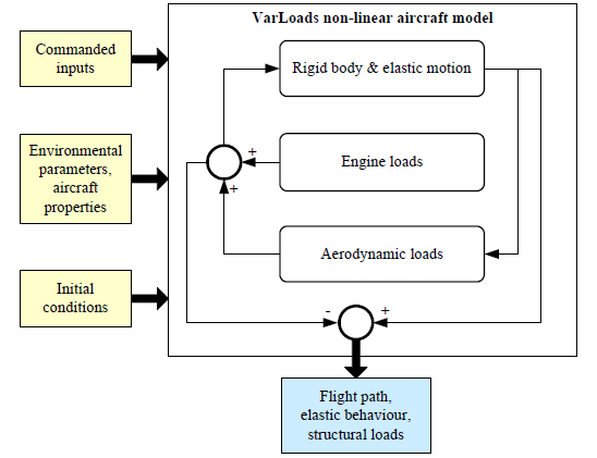
Figure 1 shows the structure of the aircraft model, which consists basically of three modules. The Rigid body and elastic motion module evaluates the rigid body and flexible response due to external forces acting on the airframe and provides the input for the calculation of the structural loads at dedicated monitoring stations. The Engine loads module computes the external loads due to engine setting and introduces them to the corresponding attachment points at the airframe. The Aerodynamic loads module evaluates external loads due to the aerodynamic pressure distribution on the airframe, which is influenced by rigid body motion, elastic deformation and external excitation, e.g. turbulence.

Figure 1: Schematic aircraft model
The simulation model processes the commanded signals, which are a superposition of pilot and flight control system inputs. The aircraft properties, such as mass distribution, as well as the environmental conditions contribute significantly to the load level. In the pre-processing routines, the aircraft parameterization is chosen according to the actual state of the aircraft for which the algorithm reconstructs the loads. Prior to the simulation, the initial conditions are determined by evaluation of the trim setting for an arbitrary maneuver. After each simulation step, the external and internal loads are superimposed and transformed to the specified monitoring stations, which coincide in the present case with the flight test measurement stations. Beside the structural loads, the flight path [6] and the elastic behavior are reconstructed in the course of the simulation and are available for further processing.
2.2 Loads Observer
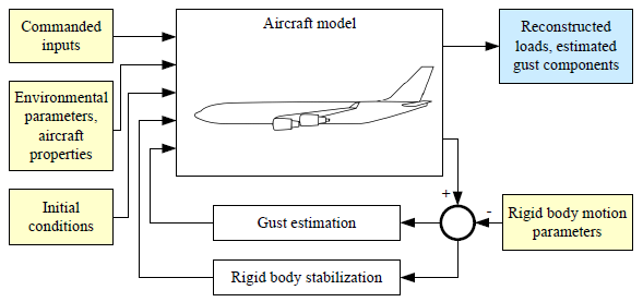
For commercial aircraft, no sensors are available for the measurement of spatial gusts. However, the aircraft’s motion is influenced significantly by turbulent atmosphere. As no signals exist reflecting this external excitation within the input data set, the VarLOADS aircraft model alone is not capable of achieving a sufficient match with the measured aircraft motion in the presence of turbulence. Hence, the model is embedded into a non-linear observer [7] as shown in Figure 2.

Figure 2: Structure of the Loads Observer
During operation, measured control inputs are fed to the aircraft model. Due to the lack of knowledge about the atmospheric turbulences encountered by the aircraft, the simulation leads to a different response than that of the real aircraft. The Loads Observer [7, 8] algorithm uses these residuals for the stabilization of the rigid body motion and for the reconstruction of gust components, which are applied as additional aerodynamic pressures at dedicated stations on the airframe. By this means, the motion of the aircraft model is forced to match the measured one and the influence of the external disturbance is taken into account for the resulting structural loads. The final output data set of the Loads Observer consists of the estimated gust components and the reconstructed loads integrated for the specified monitoring stations. Prior to the implementation into the prototype system, the Loads Observer algorithm was checked in numerous tests, in which e.g. synthetic gusts were reconstructed.
2.2 Loads Observer
Before aircraft signals can be provided as input, a pre-processing must be performed, which adapts the incoming signals according to the interface specification of the Loads Observer. The algorithm expects the data to be synchronized and equally sampled to the required step size. During the AWIATOR project, the flight test raw data were provided by the aircraft’s data acquisition unit in UDP (Universal Data Protocol) format. The signals were recorded with a different sampling rate and their own time stamp. Consequently, data pre-processing prior a provision to the Loads Observer algorithm was mandatory. This task was accomplished by the implementation of a spline interpolator, which ensured common data properties in real-time. Figure 3 shows the architecture of the pre-processing module. Before being processed, the incoming raw data set is checked for validity regarding its time stamp, but also regarding the value of each received signal in reference to a corresponding plausible band 5
width. Only in case of valid data, the pre-process is continued. As the on-line interpolation algorithm [9] requires knowledge about the development of the signal time histories, the data are written together with their respective time vector into a buffer. The sequential reception of the input data packages leads to a delay between the recorded signals of one time step. Therefore, the data are synchronized with respect to the timer value of the pre-processing module.

Figure 3: Architecture of the pre-processing module
The buffered data is passed on to the spline interpolator, which performs the smoothing and re-sampling of the input data for the Loads Observer. The interpolation and re-sampling process is depicted exemplarily for one input signal in Figure 4. Here, a short sequence of one of the input signals is shown. The data arrives sampled with a low frequency and is stored in the buffer. If the sensor step size is bigger than the recording step size of the data acquisition unit, the sample and hold mechanism leads to the recording of redundant data points, which are represented by white squares in the left sub-figure. The remaining data points
...
