Systematic model based vibration analysis of a controlled electric power steering system
chassis.tech 2017, Munich, 20-21 June 2017
M. Haßenberg, H. Henrichfreise,
Technische Hochschule Köln
Labor für Mechatronik (Cologne Laboratory of Mechatronics, CLM),
Betzdorfer Str. 2
50679 Köln
info@clm-online.de
www.clm-online.de
H. Briese, T. Schubert,
DMecS Development of Mechatronic Systems GmbH und Co. KG,
Gottfried-Hagen-Straße 20
51105 Köln
info@dmecs.de
www.dmecs.de
G. Wittler,
Hochschule Esslingen
Campus Göppingen,
Robert-Bosch-Straße 1
73037 Göppingen
gerd.wittler@hs-esslingen.de
Abstract
In [1, 2] a LQG/LTR-design is presented to control the steering wheel hand torque of electric power steering systems. Undesirable oscillations (parasitic eigenmodes) are caused by elasticities, which are not considered in the controller design. This paper shows the impact of these parasitic eigenmodes on the behaviour of the control system. Based on a detailed model analysis the root causes are shown. The results of this model analysis are used for a new control approach.
1 Introduction
To control electric power steering systems (EPS systems) different control algorithms are used. In [1, 2] a LQG/LTR-design is presented to control the steering torque of EPS systems. One advantage of this approach is that the steering feel can be adjusted independently from the design of the controller. Precondition for the application of the steering feel is a robust control system.
For this reason the robustness of the control system will be regarded in this paper. The existing controller design considers only the elasticity of the torsion bar. An EPS system contains many more elasticities. These elasticities are necessary among others for noise reduction, compensation of fabrication tolerances and decrease of shocks on the steering mechanism. Because these elasticities are not considered in the controller design, they can lead to undesired oscillations (residual eigenmodes) and also stability problems (eigenvalue spillover) [3]. The residual modes take adverse effect on the control system therefore, they are called parasitic modes.
This paper presents a systematic and model based analysis of these vibration phenomena. For this reason a detailed model will be derived in chapter 2 which contains all occurring concentrated elasticities of the steering mechanism. To outline the impact of these elasticities on the control system, the existing LQG/LTR-controller will be analysed in combination with this detailed model in chapter 3. The root causes of the problems presented in chapter 3 will be shown in chapter 4 by a detailed model analysis. Finally a first counter measure to improve the controller will be presented in chapter 5. All investigations are done using an axially parallel power steering system. The presented method can also be applied to other configurations.
2 Modeling of the Steering Mechanism
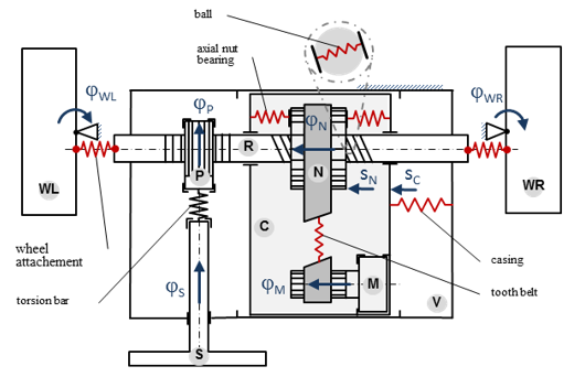
Fig. 1 shows a physical model of the steering mechanism with eight degrees of freedom (8 DOF). The individual rigid bodies are marked up with the indices S (steering), P (pinion), R (rack), N (nut), M (motor), C (casing), V (vehicle), WL (wheel left) and WR (wheel right). Elasticities in the model are considered by the torsion bar stiffness ctb (torque sensor), recirculating ball screw stiffness cnr , belt drive stiffness cmn , stiffness of the axial nut bearing cnc , stiffness of the casing attachment ccv and the stiffness of the wheel attachments crw . The mass moment of inertia and the mass of the rigid bodies are named Jx and mx , while the index is representing the body. Gear ratios are labelled with ixy , where the index x symbolizes the driving and the index y the driven body.
The equations of motion of this model have been derived, linearized and transformed into state space representation. Based on the model with eight degrees of freedom a simplified model with three degrees of freedom (3 DOF) has been determined by a model reduction.

Figure 1 Physical Model of the Steering Mechanism with eight Degrees of Freedoms
If only the torsion spring is considered and all the other connections are assumed to be rigid, the mass properties of the bodies M, N, R, P, WL and WR can be combined. From this step a model with two degrees of freedom (2DOF) results from [1, 2].
All these different models are extended by a model of the current controlled EPS-motor. These models describe the behaviour of the control plant.
3 3 Control System with different Models for the Steering Mechanism
In Fig. 2 the control system is shown which consists of a dynamic LQG-compensator and a model of the control plant. The LQG-compensator consists of an optimal state space controller (LQR) and an optimal state space observer (LQE).
...
